IoT : Communication between TI Sensortag and Zolertia Z1
My first post about IoT explained you how to set up Contiki OS and how to build and upload your first Sensortag application using Uniflash.
Now we go further and take advantages of your Sensortag by getting raw data from it and broadcast your data throw 6Lowpan protocol.
Data will be retrieve by your Zolertia Z1 and visible throw your web browser.
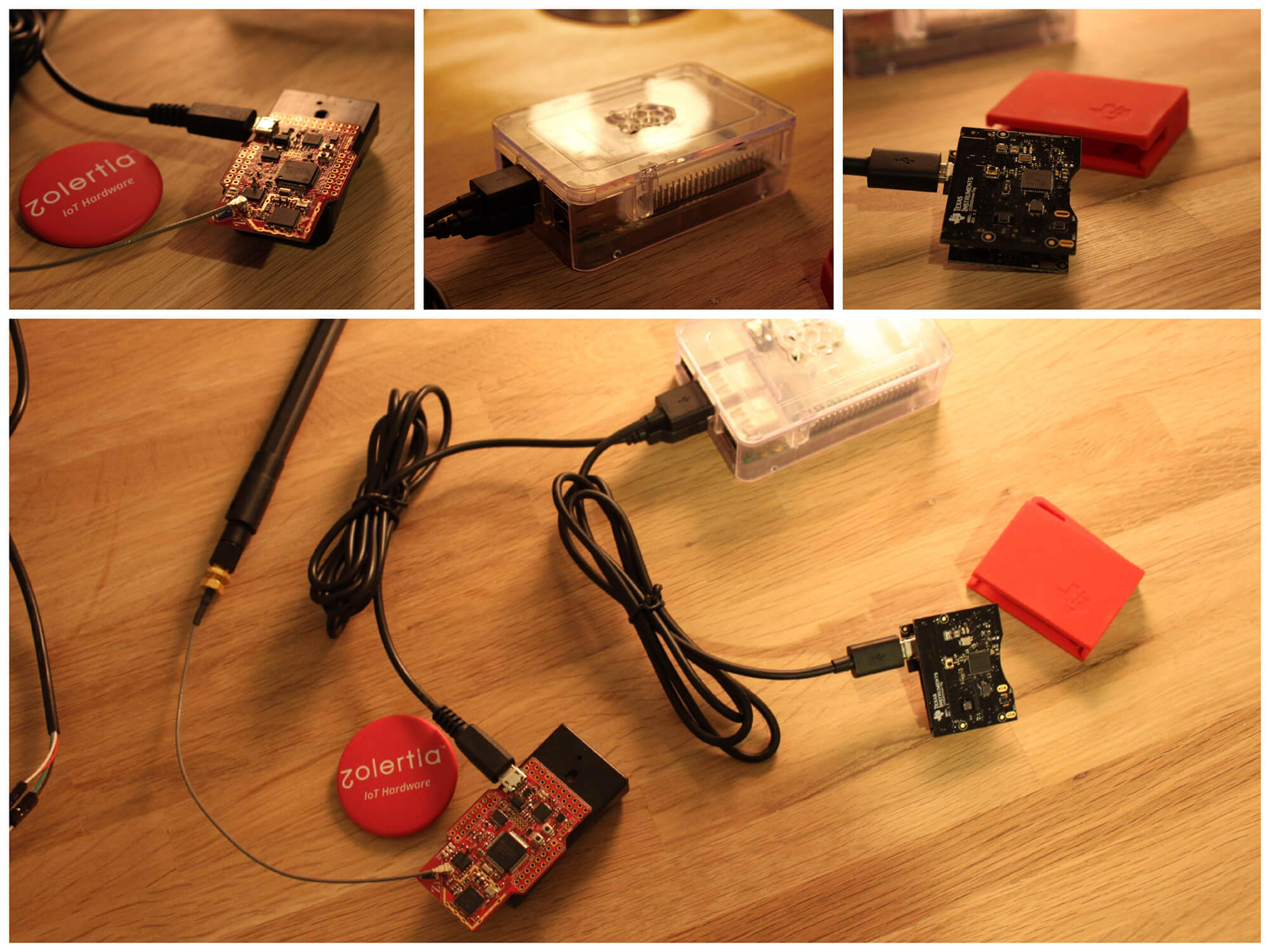
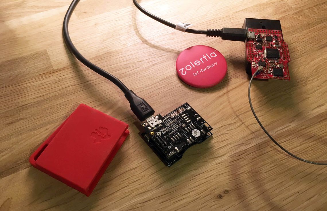
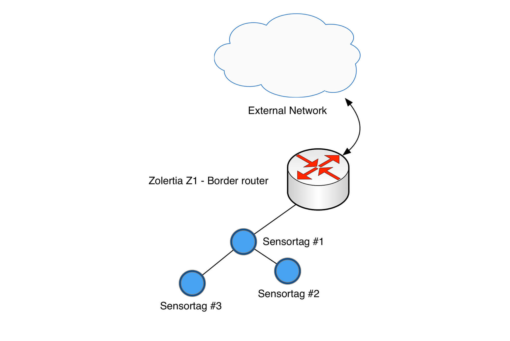
Take a look at the following plan
- Sensortag acquire raw data and broadcast it.
- Zolertia Z1 get raw data from Sensortag.
- Raspberry Pi will compile, flash Z1 and Sensortag, but if you want to use your computer, it's fine too.
Complete source code available at the end of this post.
1. Broadcast Sensortag Data
The easiest way to get data from your Sensortag is to use the example code given by Contiki Repository.
Download those files and open project-conf.h
Project files
- Makefile
- Makefile.target
- cc26xx-demo.c <-- Main program
- project-conf.h <-- Configuration file
1.1 Edit project-conf.h
We have to edit it to set up the channel and disable the Bluetooth. The goal is to 6Lowpan on Channel 26.
/*---------------------------------------------------------------------------*/
#ifndef PROJECT_CONF_H_
#define PROJECT_CONF_H_
/*---------------------------------------------------------------------------*/
/* Disable button shutdown functionality */
#define BUTTON_SENSOR_CONF_ENABLE_SHUTDOWN    0
/*---------------------------------------------------------------------------*/
/* Change to match your configuration */
#define IEEE802154_CONF_PANID            0xABCD
#define RF_CORE_CONF_CHANNEL                 26
#define RF_BLE_CONF_ENABLED                   0
/*---------------------------------------------------------------------------*/
#endif /* PROJECT_CONF_H_ */
/*---------------------------------------------------------------------------*/
Line 10 and 11 were edited.
Set 26 to RF_CORE_CONF_CHANNEL and 0 to RF_BLE_CONF_ENABLED to disable BLE.
1.2 Edit cc26xx-demo.c
Open cc26xx-demo.c. If you take a look at the code, you can see that it only read sensors and print their values periodically.
What we need is :
- Broadcast this array every 10 seconds
- Store raw data into an array
1.2.1 Broadcast it using a UDP connection
To do this, I will need a few lines of codes provided by this Contiki's example.
In the top of the file, before the methods :
// Some headers to add
#include "net/ip/uip.h"
#include "net/ipv6/uip-ds6.h"
#include "simple-udp.h"
#include <\string.h>

// Which port we are going to use
#define UDP_PORT 1234

// Declare simple_udp_connection structure
static struct simple_udp_connection broadcast_connection;
Add this method. It is implemented as a receive callback :
static void receiver(struct simple_udp_connection *c,
         const uip_ipaddr_t *sender_addr,
         uint16_t sender_port,
         const uip_ipaddr_t *receiver_addr,
         uint16_t receiver_port,
         const uint8_t *data,
         uint16_t datalen) {
  printf("Data received on port %d from port %d with length %d\n",
         receiver_port, sender_port, datalen);
}
Next lines have to be added in PROCESS_THREAD(cc26xx_demo_process, ev, data) method
uip_ipaddr_t addr;

// Register a UDP connection
// broadcast_connection	A pointer to a struct simple_udp_connection
// UDP_PORT	The local UDP port in host bytes order
// NULL	The remote IP address
// UDP_PORT	The remote UDP port in host bytes order
// receiver	A pointer to a function of to be called for incoming packets

simple_udp_register(&broadcast_connection, UDP_PORT,NULL, UDP_PORT,receiver);

// Set IP address addr to the link local all-nodes multicast address
uip_create_linklocal_allnodes_mcast(&addr);

// Send a UDP packet to a specified IP address.
// broadcast_connection	A pointer to a struct simple_udp_connection
// asend	A pointer to the data to be sent
// sizeof(asend)	The length of the data
// addrThe	IP address of the receiver
simple_udp_sendto(&broadcast_connection, asend, sizeof(asend), &addr);
Good! The we are almost ready to send our data! Only one thing is missing; Store the sensor's data into our array (asend).
1.2.2 Store Sensortag data into an array
This is the easiest part. We have to declare some array and use methods provided by Contiki to store raw data into those array!
In the header, declare some arrays:
// Light
uint16_t alight[2] = {0,0};
// MCU
uint16_t ampu[18] = {0,0,0,0,0,0,0,0,0,0,0,0,0,0,0,0,0,0};
// Altimeter/Pressure
uint16_t abmp[4] = {0,0,0,0};
// Temperature
uint16_t atmp[4] = {0,0,0,0};
// Humidity
uint16_t ahdc[4] = {0,0,0,0};
// Battery status and temperature
uint16_t abat[4] = {0,0,0,0};
// Final array containing values to broadcast
uint16_t asend[36] = {0,0,0,0,0,0,0,0,0,0,0,0,0,0,0,0,0,0,0,0,0,0,0,0,0,0,0,0,0,0,0,0,0,0,0,0};
Now you have to edit all the methods which are used to get data, and add an extra line to store the data into the corresponding array. For example, for the battery method :
static void
get_sync_sensor_readings(void)
{
  int value;

  printf("-----------------------------------------\n");

  value = batmon_sensor.value(BATMON_SENSOR_TYPE_TEMP);
  printf("Bat: Temp=%d C\n", value);
  // Add this line
  abat[0] = value;

  value = batmon_sensor.value(BATMON_SENSOR_TYPE_VOLT);
  printf("Bat: Volt=%d mV\n", (value * 125) >> 5);
  // Add this line
  abat[1] = (value * 125) >> 5;
  return;
}
Do this for every other methods :) by setting values in the right array position.
1.3 Sensortag complete code
Download the complete code here
You're now ready to build and flash your Sensortag!
1.4 Flash your Sensortag with uniflash
In my previous post, I explained how to flash your Sensortag.
Once you did it, leave your Sensortag alone :)
2. Zolertia Z1

Zolertia Z1 is really nice product which is going to be used as a border router. In this project, there's only one Sensortag, but the border router could use more than one node.
Z1 will periodically receive broadcast from its nodes and display it on an ipv6 address on a specific port.
2.1 Download Contiki border-router example
First, you have to download Contiki example of border-router. You can find the code here.
The folder contains the following files:
- border-router.c <-- Main
- slip-bridge.c <-- Contains a callback function for processing a SLIP connection request)
- httpd-simple.c <-- A simple web server
More details
The border router will receive the prefix through a Serial Line Interface Protocol (SLIP) connection and will communicate to the rest of the nodes in the RPL network. Even if we have only one Sensortag at the moment, the principle remains the same.
By default the border router hosts a simple web page. We will need to delete it and replace it by our sensors values. The webpage could be displayed by writing IPv6 address of the border router in your browser.
I will explain you how to add the missing code to get raw data from Sensortag and how to display it.
2.2 Edit border-router.c
What we need to implement:
- A UDP connection (to get data from Sensortag)
- Remove old webpage and replace with a new one
// Add the header
#include "simple-udp.h"

// Array containing the message from Sensortag
static uint16_t messagefromdevice[36];

#define UDP_PORT 1234

// Declare UDP structure
static struct simple_udp_connection broadcast_connection;


// Add this method in order to receive callback from Sensortag and store data in messagefromdevice array
static void
receiver(struct simple_udp_connection *c,
         const uip_ipaddr_t *sender_addr,
         uint16_t sender_port,
         const uip_ipaddr_t *receiver_addr,
         uint16_t receiver_port,
         const uint16_t *data,
         uint16_t datalen)
{
int i = 0;
for(i=0; i < datalen; i++) {
    messagefromdevice[i] = data[i];
}

// In PROCESS_THREAD line 335, register your UDP connection
simple_udp_register(&broadcast_connection, UDP_PORT,NULL, UDP_PORT,receiver);

// Line 115, we need a bigger array (1024 instead of 256)
static char buf[1024];
Now we create our new web page:
Lines 107 and 108
static const char *TOP = "ContikiRPL \n";
static const char *BOTTOM = "\n";
replace by :
static const char *TOP = "";
static const char *BOTTOM = "";
In
PT_THREAD(generate_routes(struct httpd_state *s)) method, line 164, we add to our page the array's content :
char signGX = ((int)messagefromdevice[2] == 1) ? '-' : ' ';
char signGY = ((int)messagefromdevice[5] == 1) ? '-' : ' ';
char signGZ = ((int)messagefromdevice[8] == 1) ? '-' : ' ';
char signAX = ((int)messagefromdevice[11] == 1) ? '-' : ' ';
char signAY = ((int)messagefromdevice[14] == 1) ? '-' : ' ';
char signAZ = ((int)messagefromdevice[17] == 1) ? '-' : ' ';

// Add our values to web page
ADD("{\"measures\":\n [{\"isActive\":%s\n,\"guid\":%s\n,\"pressure\":%d.%d\n,\"pressure_t\":%d.%d\n,\"humidity\":%d.%d\n,\"humidity_t\":%d.%d\n,\"battery\":%d\n,\"key1\":%d\n,\"key2\":%d\n,\"reed\":%d\n,\"buzzer\":%d\n,\"LED1\":%d\n,\"LED2\":%d\n,\"Radio\":%s\n,\"objtemp\":%d.%d\n,\"accelX\":%c%d.%d\n,\"accelY\":%c%d.%d\n,\"accelZ\":%c%d.%d\n,\"gyroX\":%c%d.%d\n,\"gyroY\":%c%d.%d\n,\"gyroZ\":%c%d.%d\n,\"magX\":%d\n,\"magY\":%d\n,\"magZ\":%d\n,\"light\":%d.%d \n}]}",
"true",
"My Little Sensortag",
messagefromdevice[20],messagefromdevice[21],
messagefromdevice[22],messagefromdevice[23],
messagefromdevice[28],messagefromdevice[29],
messagefromdevice[30],messagefromdevice[31],
messagefromdevice[32],
4,
1,
10,
0,
0,
0,
"6lowpan",
messagefromdevice[26],messagefromdevice[27],
signAX,abs(messagefromdevice[12]),abs(messagefromdevice[13]),
signAY,abs(messagefromdevice[15]),abs(messagefromdevice[16]),
signAZ,abs(messagefromdevice[18]),abs(messagefromdevice[19]),
signGX,abs(messagefromdevice[3]),abs(messagefromdevice[4]),
signGY,abs(messagefromdevice[6]),abs(messagefromdevice[7]),
signGZ,abs(messagefromdevice[9]),abs(messagefromdevice[10]),
0,
0,
0,
messagefromdevice[24],messagefromdevice[25]);
Comment code from line 166 to 260.
As you can see, I made a JSON file with the values we received. You're free to edit it.
Don't worry, complete code can be downloaded at the end of the post.
2.3 Build it and flash it
Go into your project directory
cd Contiki/examples/ipv6/rpl-border-router/
Save target
make TARGET=z1 savetarget
Compile and send to device
sudo make border-router.upload
Connect to device
sudo make z1-reset && sudo make connect-router
Let the last command running, or put in on a screen.
3. Last step !
Open your browser and enter the ipv6 address of your Zolertia Z1. The address is the last output of "sudo make connect-router" : http://[aaaa::c30c:0:0:1560]
Result :
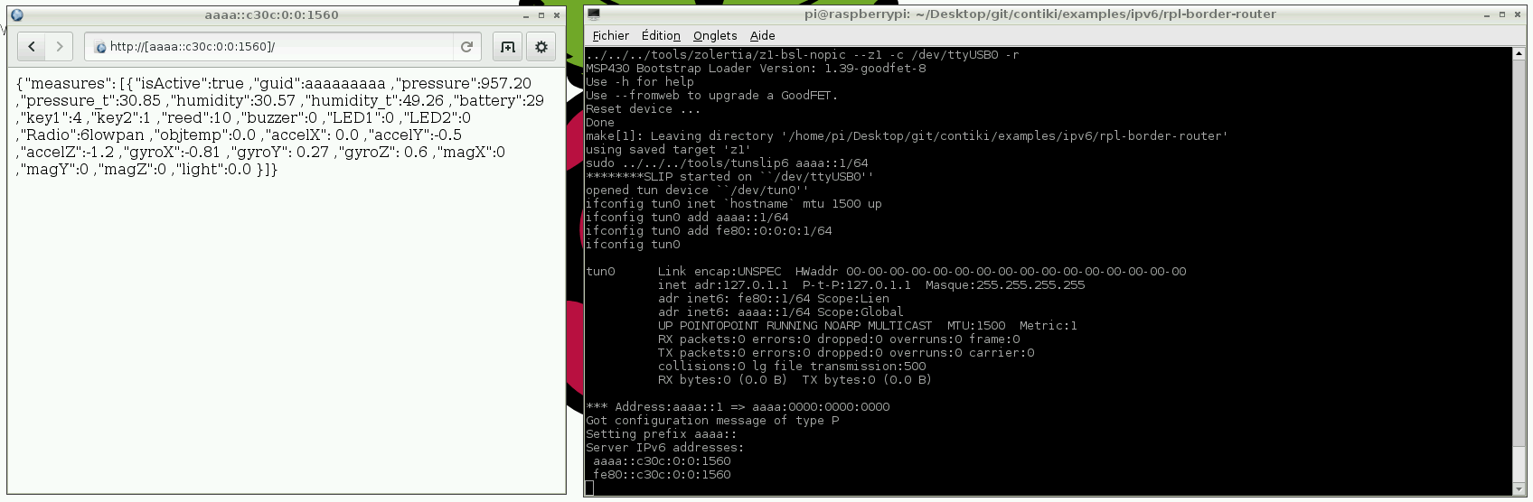
Congratulations ;)
If you have any question, do not hesitate to ask me in the comment section.
Downloads
- Sensortag code
- Zolertia Z1 code
- A complete project a friend and I made using Sensortag, Z1, Raspberry Pi and Google App engine
Member discussion